Specifying the wrong valve actuation system for a process application is an expensive mistake — not always immediately visible, but cumulative. Response time falls short of what the safety system requires. Maintenance costs compound as components designed for dry, climate-controlled environments meet the reality of a humid chemical plant. Or the electrical infrastructure simply does not exist where the valve needs to be. These are not edge-case concerns — they are the situations that push engineers to re-examine the pneumatic versus electric decision carefully rather than defaulting to whatever the previous installation used. The Pneumatic Stop Valve and the electric control valve are both capable, well-developed technologies, but they suit different operating conditions, different control requirements, and different risk profiles. The question is never which one is generically superior. It is which one fits the application.
How Each Actuation Technology Works
Compressed Air vs Electrical Drive — Different Physics, Different Behavior
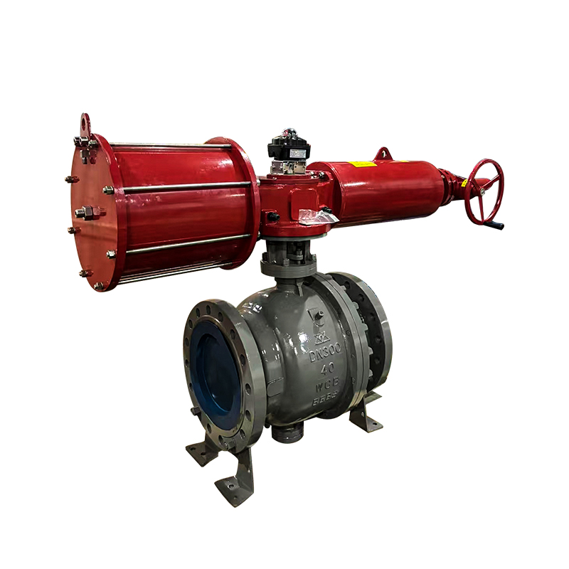
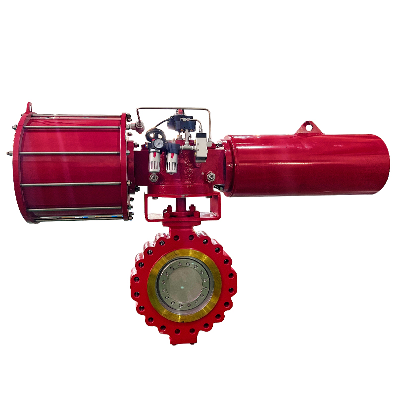
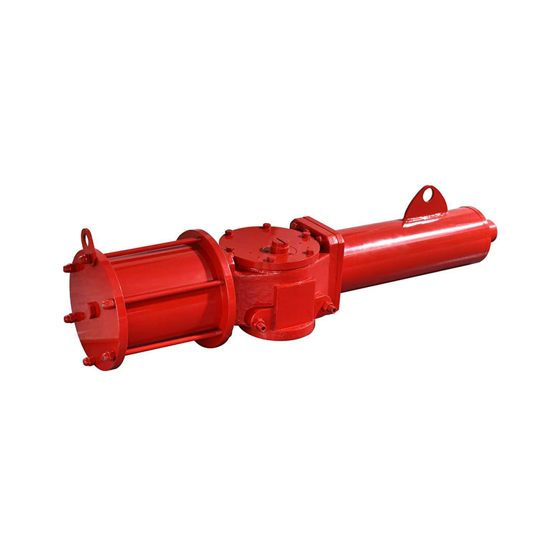
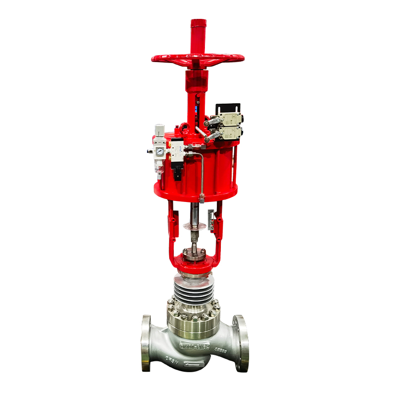
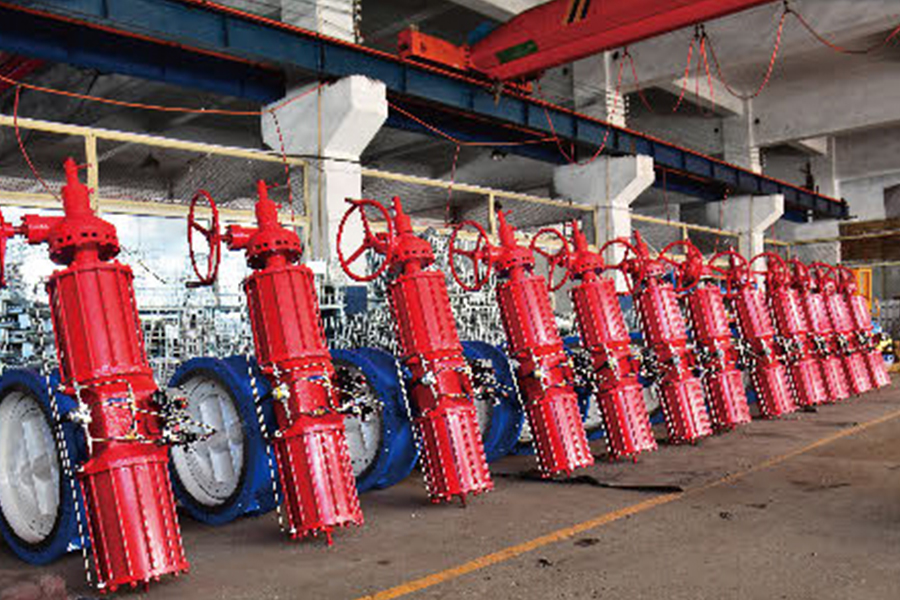
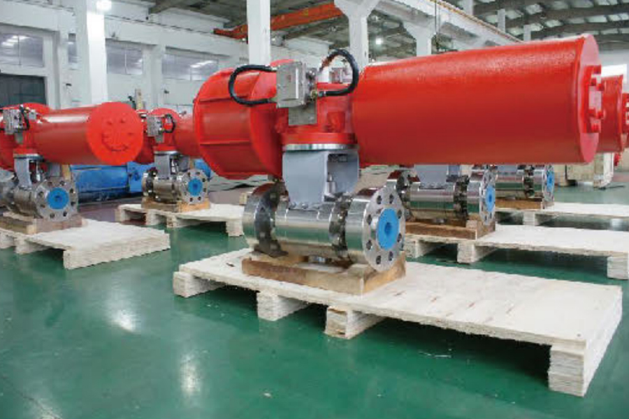
A pneumatic stop valve uses compressed air as its energy source. A solenoid valve receives an electrical signal, directs air into the actuator chamber, and the resulting pressure acts on a piston or diaphragm to move the valve stem. The mechanical action is fast, the energy storage is distributed (the compressed air system), and the actuator itself contains no electronic components beyond the solenoid.
An electric control valve uses a motor — typically a rotary actuator — to convert electrical energy directly into stem movement. The motor responds to a control signal, turns through a defined arc, and positions the valve at the commanded setpoint. Position feedback sensors confirm the actual valve position, allowing closed-loop control with high precision.
Both systems achieve valve movement. The differences lie in how quickly they respond, how precisely they can be positioned, how they behave when power or air supply is lost, and how they hold up in different environmental conditions.
Response Speed: Where Pneumatic Has a Clear Advantage
Why Milliseconds Matter in Industrial Flow Control
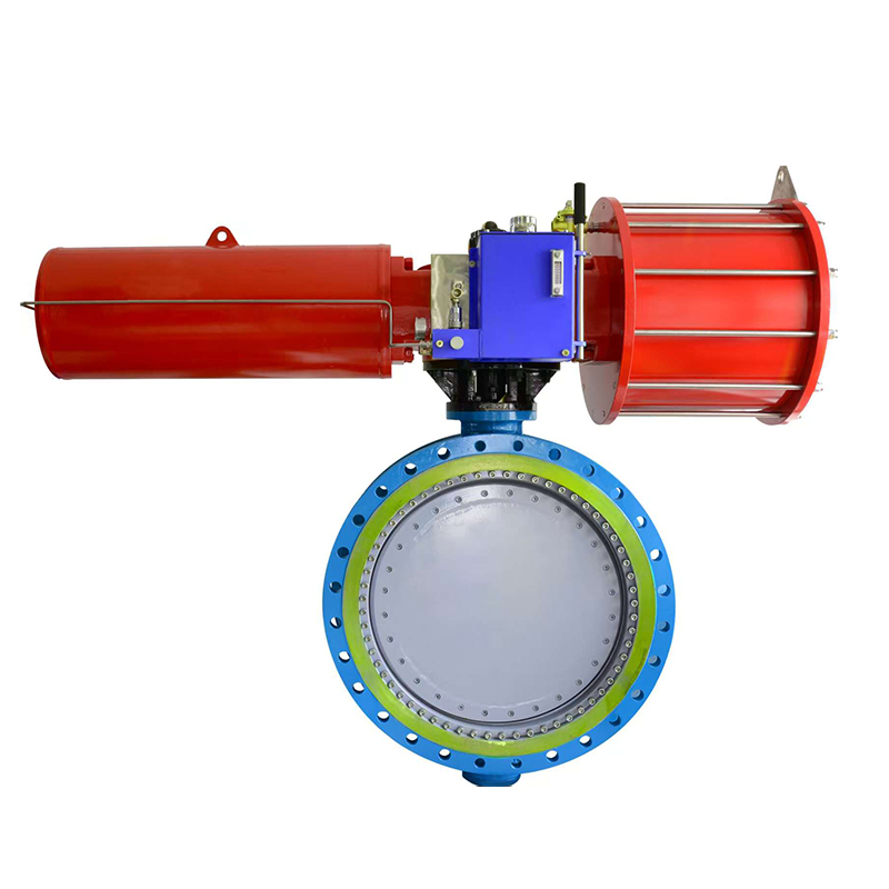
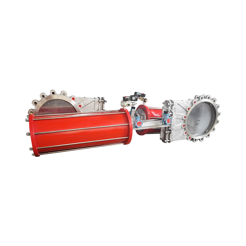
Compressed air actuators respond fast. The physics favor it — air pressure acts directly on a mechanical piston with minimal electrical or mechanical conversion steps between the control signal and the valve movement. For applications where rapid response is a functional requirement — emergency shut-down systems, surge protection, safety interlocks — pneumatic actuation is specified because it reliably delivers the response time those systems need.
Electric actuators respond more slowly. The motor must ramp up, overcome inertia, and turn through its travel arc. For proportional control of a modulating valve in a steady-state process, this speed is entirely adequate — the control loop does not demand fast response. But in scenarios where the valve must close within a short, defined time window following a trip signal, electric actuation frequently cannot match what the pneumatic system delivers.
This is not a criticism of electric actuation. It is an accurate statement of the physics involved. A pneumatic emergency shut off valve in a safety-critical application is specified for speed as its primary functional requirement — and pneumatic actuation meets that requirement in ways that electric systems cannot match.
Precision and Control: Where Electric Actuation Has the Edge
Position Accuracy Matters in Modulating Applications
Electric control valves are inherently better suited to proportional or modulating control. The motor can be commanded to any position in its travel range with a control signal, and position feedback from the actuator confirms where the valve stem actually is. This allows the control system to hold a valve at thirty percent open, seventy percent open, or any intermediate position — maintaining precise flow control as process conditions change.
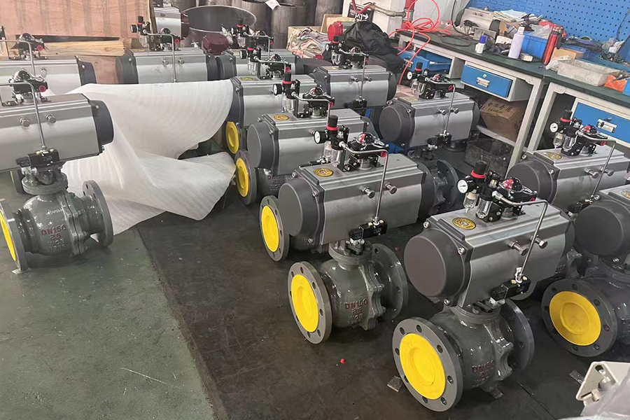
Pneumatic actuators can also be configured for modulating control using a positioner — a device that takes a control signal and adjusts the air supply to the actuator to achieve the commanded position. This works well and is widely used in process industries. But the positioning precision and repeatability of a well-configured electric actuator is generally tighter, particularly in small-signal situations where the control loop is making fine adjustments.
For applications where tight flow regulation is the primary requirement — chemical dosing, temperature control loops, precision batch processing — the electric control valve's positioning accuracy is a genuine advantage.
Fail-Safe Behavior: A Critical Design Decision
What the Valve Does When Something Goes Wrong
In safety engineering, the behavior of a valve during a loss-of-power or loss-of-air event is not a secondary detail. It is part of the safety function. The two actuation types handle this very differently.
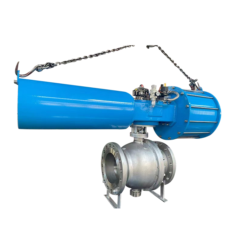
Pneumatic fail-safe behavior is engineered through spring-return actuator design. When compressed air supply is lost — whether by design (solenoid de-energized) or by fault (air supply failure) — the spring drives the valve to its preset fail position. Fail-closed sends the valve to the closed position on air loss. Fail-open keeps the valve open on air loss. The choice is made during system design by selecting the appropriate spring-return configuration.
This spring-return mechanism is passive and mechanical — it operates without any power, without any control signal, and without any electronic components functioning. It is inherently reliable in power loss scenarios.
Electric fail-safe behavior typically involves either holding position on power loss (the motor stops where it is), or using a battery-backup system to drive the valve to a defined position. Battery-backup fail-safe electric actuators exist and perform this function, but they introduce an additional component — the battery — that requires maintenance and has a defined service life.
For safety interlock and emergency shut-down applications, the pneumatic spring-return design is typically preferred precisely because its fail-safe behavior requires no power and no backup system to function.
Environmental Suitability: Pneumatic in Harsh Conditions
Where Electrical Systems Create Complications
Hazardous area classifications — zones where flammable gases, vapors, or dusts may be present — impose specific requirements on electrical equipment. Electric actuators in these zones must be certified for explosion protection, which increases cost, limits available options, and adds complexity to installation and maintenance.
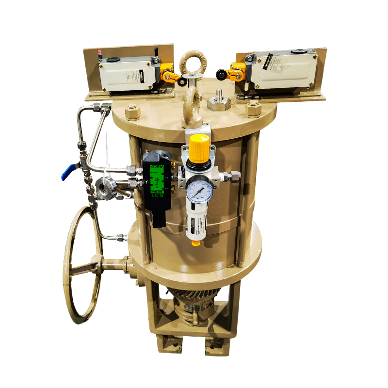
Pneumatic actuators contain no electrical components in the actuator body itself. The only electrical element in a pneumatic system that requires hazardous area rating is the solenoid valve, which is a small, standardized component with widely available Ex-rated versions at modest cost.
This distinction matters considerably in oil and gas, chemical processing, pharmaceutical manufacturing, and similar industries where large portions of the process area carry hazardous area classification. Installing pneumatic system control valve products in these zones is straightforward compared to the certification and cost requirements for equivalent electric actuators.
Beyond explosion protection, pneumatic actuators also handle high-temperature environments, washdown environments, and outdoor installations more tolerantly than electric actuators with position sensors and motor windings that are sensitive to moisture and thermal stress.
Infrastructure Requirements: The Hidden Cost Factor
What Each System Needs to Operate
Neither pneumatic nor electric actuation operates in isolation. Both require infrastructure, and the availability and cost of that infrastructure at the installation site shapes the practical decision as much as the valve's functional performance does.
Pneumatic systems require:
- A compressed air supply at appropriate pressure and cleanliness for the actuator type
- Air distribution piping to each valve location
- Moisture separators and filters at the supply point to protect actuators and solenoids
- Regular monitoring of air supply pressure and quality
Electric systems require:
- Power supply wiring to each valve location
- Cable management and conduit in process environments
- Electrical safety certifications in hazardous areas
- Control wiring for position feedback and command signals
In facilities where compressed air infrastructure is already installed — which includes most manufacturing and process plants — adding pneumatic valve actuation is straightforward. In facilities without existing air supply, the cost of installing a compressed air system is a real additional capital expense that changes the economics.
Conversely, in facilities with strong electrical infrastructure but limited or unreliable compressed air supply, electric actuation is the more practical choice.
Energy Cost Over the Operating Life
How Operating Economics Differ Between the Two Systems
Compressed air is not a free energy source. Compressing air consumes electrical energy, and the efficiency of air compression and distribution is lower than direct electrical drive. Over a long operating life, the energy cost of maintaining a compressed air system can exceed the energy cost of operating electric actuators directly.
This does not make pneumatic systems uneconomical — in facilities where compressed air is already a utility serving multiple functions, the incremental cost per valve actuator is modest. But in a greenfield installation where compressed air is being installed specifically for valve actuation, the energy operating cost over a ten-year horizon is worth calculating before committing to the infrastructure investment.
For facilities with a small number of valves in a localized area where compressed air would only serve those valves, electric actuation may present a more favorable total cost of ownership despite the higher initial actuator cost. For large process plants where compressed air is a distributed utility, the calculation typically favors pneumatic.
Comparing the Two Actuation Types Across Key Factors
A side-by-side view across the variables that engineering and procurement teams typically weigh:
| Comparison Factor | Pneumatic Stop Valve | Electric Control Valve |
|---|---|---|
| Response speed | Fast — suitable for safety systems | Slower — suitable for modulating control |
| Positioning precision | Good with positioner | High — inherent to motor drive |
| Fail-safe behavior | Spring-return — passive, reliable | Battery backup or hold-position |
| Hazardous area suitability | Strong — minimal Ex requirements | Higher certification cost |
| Energy efficiency | Lower (air compression losses) | Higher (direct electrical drive) |
| Infrastructure requirement | Compressed air system | Electrical power and control wiring |
| Environmental tolerance | High — handles moisture and temperature well | Moderate — sensitive to harsh conditions |
| Maintenance complexity | Moderate — air filters, seals | Moderate — motor and electronics |
| Initial cost | Lower actuator cost | Higher actuator cost |
| High-cycle suitability | Strong | Good with appropriate motor sizing |
Neither system wins across every row. The picture that emerges is that pneumatic actuation suits speed-critical, safety-critical, and harsh-environment applications particularly well. Electric actuation suits precision modulating control, energy-efficiency priorities, and locations where compressed air is not practical.
Which Applications Typically Favor Each System?
Matching Actuation Type to Process Function
Applications where pneumatic stop valves are the natural specification:
- Emergency shut-down and safety interlock systems requiring fast, reliable response
- Hazardous area process plants where electrical certification costs are a concern
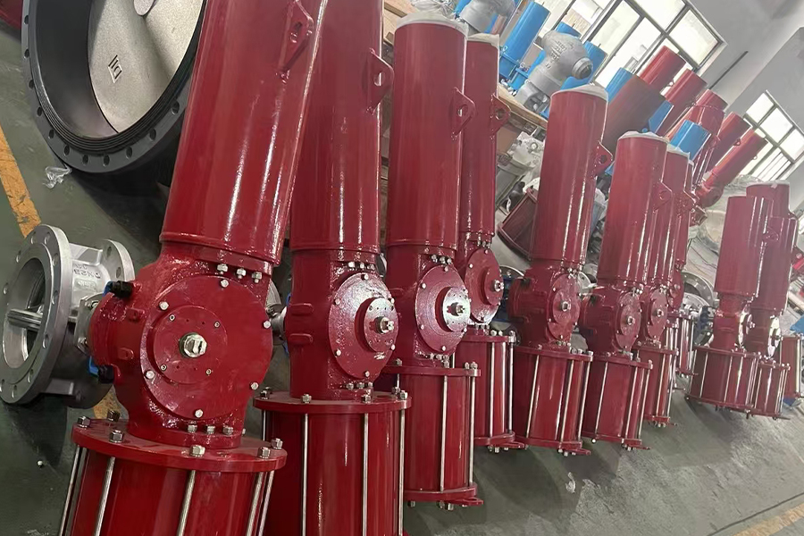
- High-cycle applications in manufacturing and packaging lines
- Outdoor or washdown environments where moisture resistance matters
- Upstream oil and gas where compressed air infrastructure is standard
Applications where electric control valves are the natural specification:
- Precision flow and pressure control loops requiring fine positioning
- Facilities without existing compressed air infrastructure
- Energy-efficiency focused projects where operating cost is a primary metric
- HVAC and building automation where electrical infrastructure is already in place
- Remote locations without convenient compressed air supply
Applications where the choice is genuinely open:
- General industrial isolation service with moderate cycle rates
- Water and wastewater treatment where both systems are used extensively
- Food and beverage processing where hygiene and washdown requirements shape the decision as much as actuation type
Working With a Supplier Who Understands the Application
The decision between pneumatic and electric actuation is not resolved by product specifications alone — it requires matching the valve's functional characteristics to the actual conditions of the installation, the safety requirements of the process, and the infrastructure available at the site. Zhejiang Wisley Automatic Valve Co., Ltd. develops pneumatic stop valves and related flow control products for industrial automation applications, with product configurations covering fail-safe behavior, hazardous area service, and high-cycle industrial use. Their engineering and application team can discuss actuation selection against specific process requirements rather than offering a generic product recommendation. If you are working through valve actuation specifications for a new installation, a safety system upgrade, or a large-scale procurement project, reaching out to discuss the application details is a productive starting point for selecting the configuration that fits the real demands of the process.