

 English
 русский



A pneumatic valve that fails in service rarely fails because of a manufacturing defect. It fails because something went wrong during installation — the flow direction was reversed, the pipe alignment put mechanical stress on the valve body, the thread seal was applied carelessly, or the system was pressurized before a proper leak check was done. A Pneumatic Stop Valve is a precision control component, and it needs to be installed with the same care that any critical system element demands. Getting the installation right from the start is far less expensive than tracing a fault back to the valve three months into operation when the system is down and the pressure to get it running again is high.
Understanding What a Pneumatic Stop Valve Does Before Installing It
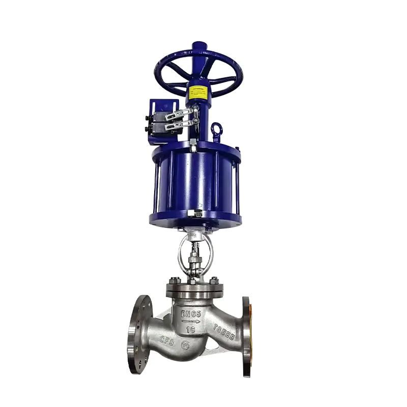
The Valve's Function Determines Every Installation Requirement
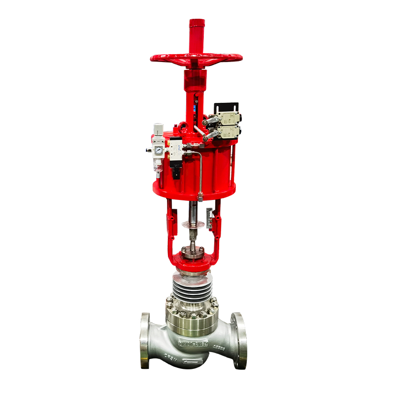
A stop valve in a pneumatic system does exactly what its name implies — it stops flow. When actuated, it closes the passage completely, cutting off compressed air to a downstream circuit. When deactuated, it opens and allows flow to resume. This on/off control function is used for system isolation, emergency shutdown, sequence control, and circuit protection.
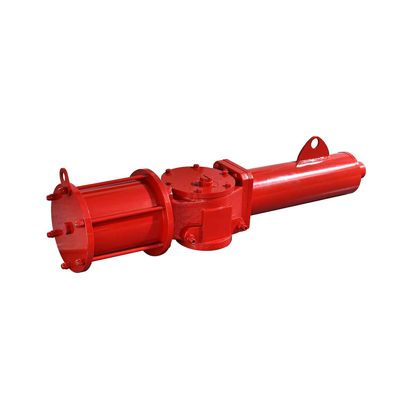
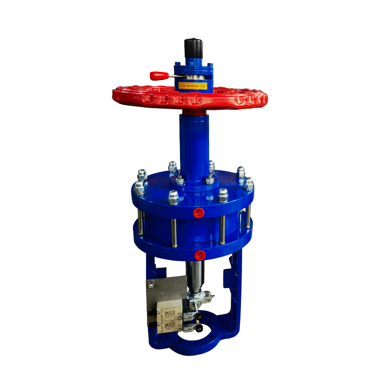
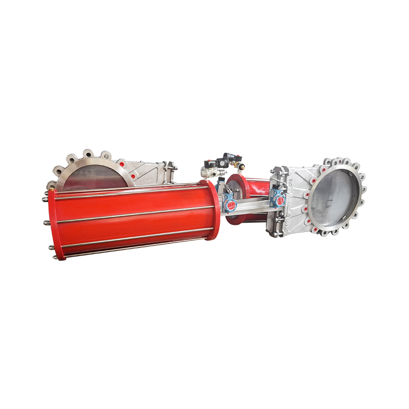
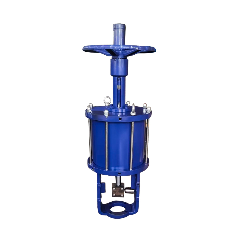
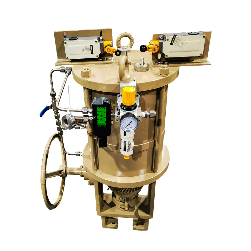
The actuator driving this movement is typically pneumatic itself — a cylinder or diaphragm that responds to a pilot signal — or it may be solenoid-controlled with a pneumatic actuating mechanism. Either way, the valve needs to be installed in the correct flow direction, connected to the right supply and signal ports, and mechanically secured so that it holds position without vibration-induced loosening.
Understanding this functional picture before installation prevents the more common errors, which are almost always about orientation and connection rather than the mechanical fitting process itself.
Safety Preparations Before Any Work Begins
Depressurization Is Not Optional — It Is the Starting Point
Working on any pressurized system without verifying that it is fully depressurized creates risk. Compressed air carries significant stored energy, and a sudden release during installation can cause injury and damage to both the valve and the surrounding equipment.
Required preparations before starting:
- Shut down the compressed air supply to the relevant circuit
- Vent any residual pressure through the drain or exhaust port — do not assume pressure has dissipated just because the supply is off
- Verify pressure at zero using a gauge on the circuit before disconnecting anything
- Lock out the air supply if the installation is happening in an environment where others could inadvertently re-pressurize the line
- Identify the correct valve specification — rated pressure, port size, flow direction, and actuator type — and confirm it matches the system requirements before fitting
This preparation stage takes a few minutes. Skipping or rushing it creates the conditions for installation errors that are invisible until the system is back under pressure.
Checking the Valve Before Installation
Does the Valve Match What the System Needs?
Receiving a valve and fitting it without checking specifications is a common source of problems. Pneumatic valves are available across a wide range of pressure ratings, port configurations, and flow capacities, and a valve that is close to the right specification is not the same as the right valve.
Before installation, verify:
- Pressure rating: Confirm the valve is rated for the operating and peak pressures of the system it will be installed in
- Port sizes: Match the thread standard and port size to the pipe or fitting it will connect to — a mismatched thread will either not seal or will seat incorrectly
- Flow direction marking: Almost all stop valves have an arrow or IN/OUT marking on the body indicating the intended flow direction. Note which end is which before beginning installation
- Actuator function: For a Pneumatic Emergency Shut Off Valve, confirm whether the valve is normally open or normally closed in its rest state — this determines which position it goes to on loss of air signal
- Seal condition: Check that the valve seals and O-rings are in good condition and have not been damaged in transit or storage
A five-minute pre-installation check catches specification mismatches before they become a removal and replacement job.
Preparing the Pipe and Installation Site
Clean Piping Is as Important as a Quality Valve
Contamination in a pneumatic line damages valve internals and creates sealing problems from the moment the system is pressurized. Metal swarf from pipe cutting, debris in older lines, and residual moisture from improper air treatment all end up in valve seats and actuator mechanisms if the piping is not properly prepared.
Steps for pipe preparation:
- Cut pipe cleanly and deburr the cut end — a burr left on the pipe end can damage valve seat seals during assembly and will shed particles into the flow stream
- Clean the pipe interior — a rag pull or compressed air blow-down removes debris from new pipe; older lines may need more thorough flushing
- Verify pipe alignment — the pipe should approach the valve port straight, without angular offset that would put the valve body under bending stress when tightened
- Check the mounting position — the valve should be accessible for future operation and maintenance, and oriented so that the actuator can move freely without obstruction
Getting the pipe ready takes time. It also prevents the contamination-related failures that are frustratingly common in systems where the valve installation was done quickly without attention to the surrounding pipework.
Applying Thread Sealant Correctly
Thread Sealing Is Where Many Leaks Start
A threaded connection that is not properly sealed will leak under pressure. The leak may not be dramatic — sometimes it is a slow loss that only shows up as reduced system efficiency over time — but it is always avoidable.
For pneumatic system connections:
- Use PTFE thread tape or an appropriate thread compound rated for pneumatic service — not pipe dope formulated for water or gas, which may swell or degrade in compressed air service
- Apply tape by wrapping in the direction of the thread — pull the tape tight as you wind so it seats into the thread form, and overlap each pass slightly
- Do not apply thread sealant to the opening threads at the pipe end — a small gap at the entry prevents sealant from being pushed into the valve body by the threading action
- Apply sealant to the male thread, not the female port — this keeps the sealant on the outside of the connection where it cannot migrate inward
After applying sealant, thread the connection by hand until it seats, then tighten with a wrench to the appropriate torque. Over-tightening cracks valve bodies; under-tightening allows leaks. A good practice is to tighten firmly to hand resistance, then apply a short additional turn rather than continuing to drive until resistance peaks.
Installing the Valve in the Correct Orientation
Flow Direction Errors Are Among the Costliest Installation Mistakes
A stop valve installed in the wrong flow direction may appear to function initially but will underperform, leak, or fail prematurely. The internal geometry of standard stop valves is not symmetric — the seat, plug, and sealing surfaces are designed for flow in one specific direction.
Installation orientation requirements:
- Position the valve so the arrow on the body points in the direction of flow through the system
- For a Pneumatic System Control Valve used in a branched circuit, confirm which port is the supply side and which is the outlet before connecting
- In vertical installation positions, note whether the valve specification calls for a particular up/down orientation — some actuator types are sensitive to gravity effects on the moving components
- Secure the valve body against rotation and vibration using the mounting provisions on the valve or by supporting the adjacent piping — a valve that vibrates at operating frequency will loosen its connections over time
Connecting the Pneumatic Actuator Supply
The Actuator Signal Connection Determines How the Valve Responds
The valve body handles the main flow. The actuator handles the control signal that opens and closes it. Getting the actuator connection right is what makes the valve responsive to the system's control logic.
Steps for actuator supply connection:
- Connect the pilot air supply to the correct port on the actuator — the signal port is usually labeled separately from the main flow ports
- Verify the pilot pressure range matches the actuator's operating specification — too low a pilot pressure and the actuator will not fully stroke; too high and it may damage the actuator seals over time
- For solenoid-controlled pneumatic valves, confirm the electrical supply voltage matches the solenoid coil rating before connecting power
- Route control air tubing so it cannot be snagged, kinked, or exposed to heat sources that would affect the tubing material over time
- Install any required mufflers or exhaust silencers on the actuator exhaust port before commissioning — leaving the exhaust port open without a muffler allows contaminants into the actuator on the intake stroke
Commissioning: How to Bring the System Up Safely
Slow Pressurization Catches Problems Before They Become Failures
Once the valve is installed and all connections are made, commissioning should be done gradually. A rapid full-pressure start does not give the installation time to reveal small leaks or misalignments before they are under full load.
Commissioning sequence:
- Bring system pressure up slowly using a pressure regulator — introduce pressure in stages, pausing to check for leaks at each increment
- Check all threaded connections with a leak detection solution or electronic leak detector while at partial pressure
- Cycle the valve through its full stroke — open to closed and back — several times while monitoring for correct operation and checking for any unusual sounds or resistance
- Bring to operating pressure and repeat the leak check
- Verify the valve responds correctly to its control signal — that it opens when signaled to open and closes fully when signaled to close
- Check the actuator for full stroke completion — a valve that does not fully open or close may have an under-pressured actuator supply or a misaligned connection
A record of the commissioning checks — what was tested, what was found, what was adjusted — is useful for maintenance reference and for diagnosing any issues that develop later.
Common Installation Errors and How to Avoid Them
A reference for the errors that show up repeatedly in pneumatic valve installations:
| Installation Error | Consequence | Prevention |
|---|---|---|
| Wrong flow direction | Valve underperforms or fails to seal | Check arrow on body before fitting |
| Over-tightened thread connection | Cracked valve body | Tighten firmly, avoid excess torque |
| Thread sealant in valve port | Contaminated seat, sealing failure | Apply to male thread only, avoid entry threads |
| Pipe misalignment at valve port | Mechanical stress, early seal failure | Ensure straight alignment before tightening |
| Rapid pressurization at startup | Hidden leaks become failures under load | Gradual pressure increase, staged leak check |
| Pilot pressure outside actuator range | Incomplete stroke, actuator damage | Verify pilot pressure spec before connecting |
| Missing actuator exhaust muffler | Contamination ingress to actuator | Fit muffler before commissioning |
| Valve installed in vibrating pipe without support | Loosening connections over time | Support pipe and mount valve securely |
These errors are generally easy to avoid. They happen when installation is rushed or when the installer does not check the valve specification before fitting.
Getting Installation Support and Sourcing Reliable Components
A correctly installed pneumatic stop valve operates reliably for years without attention. An incorrectly installed one creates faults that are difficult to diagnose and expensive to fix, particularly in systems where the valve is in an inaccessible location or where downtime is costly. The installation process itself is not complex — it follows a logical sequence of preparation, fitting, connection, and commissioning — but each step needs to be done with attention to the specific requirements of the valve and the system it sits in. For engineers and procurement teams sourcing pneumatic stop valves, system control valves, and emergency shut-off components for industrial automation, Zhejiang Wisley Automatic Valve Co., Ltd. produces pneumatic valve products with technical documentation to support correct installation and commissioning. Contacting their team to discuss product specifications, system compatibility, or technical support requirements is a practical step toward equipment that performs reliably from installation day forward.