An emergency shutdown is supposed to stop a process safely. What engineers and maintenance teams frequently discover instead is that the shutdown event itself creates a secondary problem: fluid escaping from lines that were under pressure moments before, filling spaces it should not reach, contaminating adjacent systems, or creating conditions that the original shutdown was intended to prevent. The pressure dynamics inside a pneumatic system during a rapid stop are not passive — they are actively disruptive, and without the right valve architecture in place, leakage is a predictable consequence rather than an exceptional one. Understanding why this happens, and how Pneumatic System Control Valve and Pneumatic Emergency Shut Off Valve configurations prevent it, is the foundation of reliable industrial shutdown safety design.
Why Fluid Leakage Happens During Emergency Shutdowns
The Pressure Conditions That Make Leakage Likely
A pneumatic system in normal operation maintains a controlled pressure equilibrium. Upstream supply pressure, downstream working pressure, and the positions of active valves are all in a managed relationship. When an emergency shutdown occurs — whether triggered by a safety sensor, a manual stop command, or a power interruption — that equilibrium collapses rapidly and asymmetrically.
The supply pressure drops suddenly. But the pressure stored in actuators, cylinders, downstream pipework, and flexible hose segments does not disappear at the same rate. This residual pressure seeks a path to equalize, and in the absence of controlled isolation, that path is often through connections, seals, or valve clearances that were adequate under normal operating conditions but were never designed to handle the dynamic pressure reversal that a rapid shutdown creates.
Backflow as a Specific Leakage Mechanism
One of the more damaging leakage modes during emergency shutdowns is backflow — fluid moving in the reverse direction through lines that normally carry it only forward. When upstream pressure drops suddenly while downstream actuators or reservoirs still hold pressure, the pressure gradient temporarily reverses. Fluid that should remain in the working circuit pushes back toward the supply side, past check valves that may not seat instantly, through control valve bodies whose spool positions were designed for forward flow, and into sections of pipework where its presence creates contamination, corrosion, or operational problems in the next cycle.
Backflow is particularly problematic in systems that process or convey different fluid types in separate circuits. A reversal that allows one fluid to enter a circuit designed for another creates cross-contamination that may not be immediately apparent but will degrade system performance and component longevity over time.
Seal Behavior Under Sudden Pressure Change
Seals in pneumatic system components are designed to perform reliably under sustained, predictable pressure loading. The sudden pressure changes that accompany emergency shutdowns impose dynamic loading conditions that differ significantly from steady-state operation. Elastomeric seals that maintain effective closure under normal pressure differentials can experience momentary deformation or incomplete seating under rapid transient loads.
This is not a seal quality failure — it is a consequence of using components at the edge of their design envelope. Systems that undergo frequent emergency stops will show accelerated seal wear at connection points and valve bodies, and this wear compounds over time. Preventing the pressure transients that cause this dynamic loading is a more effective long-term strategy than treating the resulting seal degradation as a maintenance inevitability.
How Pneumatic Systems Behave at the Moment of Shutdown
Pressure Drop Is Not Instantaneous or Uniform
When a shutdown signal reaches a pneumatic system, the response is not simultaneous across the entire system. Control signals travel at electronic speed, but fluid pressure changes propagate at the speed of sound in the medium — which in a compressed air system means pressure changes arrive at different parts of the system at slightly different times depending on distance from the source and the acoustic characteristics of the pipework.
This non-uniformity creates transient pressure gradients that can exceed the steady-state pressure differential the system was designed around. A section of pipe that is normally at working pressure may briefly experience a higher differential pressure during the shutdown transient than it ever experiences during normal operation, because the upstream pressure drops before the downstream pressure has equalized.
Control Valve Response Time and Its Safety Implications
Pneumatic System Control Valve response to shutdown commands is not instantaneous. The valve receives its signal, actuates, and moves to the commanded position over a finite time window. In well-maintained systems with correctly specified actuators, this response is fast. But it is never zero, and during the interval between the shutdown command and the valve reaching its closed position, fluid continues to flow — potentially through circuit paths that are no longer fully managed.
The practical consequence is that the order of valve closure in a complex system matters. If an upstream supply valve closes before downstream isolation valves reach their commanded positions, the pressure dynamics between the two create exactly the transient conditions that cause leakage. System design must account for this sequencing, and valve selection must ensure that the response characteristics of each component are appropriate for its position in the shutdown sequence.
Main Causes of Fluid Leakage in Emergency Shutdowns
Pressure Imbalance Between System Segments
The most common root cause of shutdown-related leakage is simply pressure imbalance — different segments of the system reaching equilibrium at different rates, with the differential driving fluid through any available path. This is a system-level phenomenon that cannot be fully resolved at the component level alone. It requires both proper valve placement to isolate segments and valve specifications that ensure rapid, reliable closure when isolation is needed.
Pressure imbalance is amplified in systems with:
- Long pipe runs between valve stations, which create significant fluid inertia during flow
- Variable-diameter pipework that changes flow velocity and pressure distribution
- Multiple branches that respond differently to the same shutdown signal
- Reservoirs or accumulators that hold significant stored energy even after supply is interrupted
Valve Backflow and Reverse Pressure
Beyond the transient conditions at shutdown, some system configurations create sustained reverse pressure conditions after the shutdown event. If downstream actuators or process equipment continue to hold pressure after the supply is isolated, and if the isolation is not complete enough to prevent reverse flow, that stored energy drives fluid backward through the system.
Check valves in the circuit are supposed to prevent this, but check valves have cracking pressures — minimum differential pressures required to open the valve in the forward direction, and correspondingly, minimum back-pressures required to hold it closed. In dynamic conditions where the pressure differential reverses rapidly, some check valve designs may not seat fully before fluid has already passed in the reverse direction.
Seal Degradation Under Repeated Shutdown Cycling
Systems that undergo regular emergency shutdowns — whether in test cycling, production environments with frequent stops, or safety systems that activate regularly — accumulate seal stress that manifests as progressive degradation of sealing effectiveness. Each shutdown event imposes a transient load spike on sealing surfaces. The cumulative effect over many cycles is micro-deformation of seal materials and changes in the contact geometry between seals and their mating surfaces.
This degradation is gradual and often goes unnoticed until leakage becomes observable. The maintenance implication is that systems with high emergency shutdown frequency require more frequent seal inspection than equivalent systems operating at lower cycle rates.
Safety Engineering Principles for Leakage Prevention
Fail-Safe Design as the Structural Foundation
Fail-safe design in pneumatic systems means that the default condition of every valve — the position it adopts when power, signal, or control air is removed — is chosen based on which position creates the safer outcome for the process and the surrounding environment. A valve that defaults to closed on signal loss prevents fluid from continuing to flow when the system stops. A valve that defaults to open allows pressure to vent safely if that is the safer outcome for the specific circuit.
The distinction matters because the same physical event — loss of control signal — should ideally drive all valves toward the configuration that prevents leakage and protects downstream equipment. This requires deliberate valve selection based on failure mode analysis, not simply specifying the most convenient default position for normal operation.
Pressure Isolation as a Leakage Control Strategy
Isolating pressure in defined segments of the system during shutdown prevents the cross-system pressure differentials that drive leakage. Strategically placed isolation valves divide the system into zones that can be independently depressurized in a controlled sequence rather than relying on a single upstream isolation point.
Effective pressure isolation design considers:
- Which segments of the system can be safely depressurized together without creating interfering pressure gradients
- The sequence in which segments should be isolated to minimize transient pressure spikes
- The venting or controlled release path for each segment as pressure is reduced
- Whether any segments contain stored energy in accumulators or actuators that requires active managed release rather than passive venting
Controlled Depressurization vs Sudden Isolation
A controlled depressurization strategy reduces pressure in a managed way rather than isolating supply suddenly and allowing downstream pressure to self-equalize through whatever path is available. This approach uses valve configurations that can throttle the rate of pressure reduction, keeping the system within its designed pressure envelope throughout the shutdown sequence rather than creating momentary exceedances.
Controlled depressurization is more complex to implement than simple isolation, but in systems handling hazardous fluids, high pressures, or situations where sudden pressure changes could damage connected equipment, the additional complexity is clearly justified by the reduction in leakage risk and equipment stress.
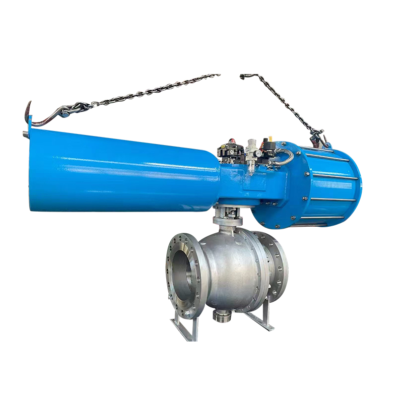
How Pneumatic Control Valves Prevent Shutdown Leakage
Flow Regulation and Pressure Stability During Shutdown
A Pneumatic System Control Valve positioned correctly in a circuit provides active pressure management rather than passive flow blockage. During a shutdown sequence, the control valve can be driven through a calibrated closure profile — reducing flow progressively rather than switching off abruptly — which limits the transient pressure spike at the point of isolation and reduces the energy available to drive fluid through seals and connections in adjacent circuit sections.
This active management capability requires that the control valve's actuator responds accurately to the shutdown command and moves through the closure profile without hunting or oscillation. Actuator sizing, positioner calibration, and supply air pressure to the valve actuator all affect whether the valve can execute the commanded closure profile reliably under emergency conditions.
Preventing Reverse Flow Through Valve Design
Control valves with internal check features or combined check valve assemblies prevent reverse flow through the valve body when downstream pressure exceeds upstream pressure. This is particularly important in systems where shutdown creates sustained reverse pressure conditions rather than simple pressure equalization.
The effectiveness of reverse flow prevention depends on how quickly the check function engages — a slow-seating check allows some backflow before isolation is achieved — and on the sealing integrity of the check element under the reverse pressure it must resist. Valve selection for applications with known reverse pressure exposure should include explicit evaluation of check performance under those conditions, not just forward-flow specifications.
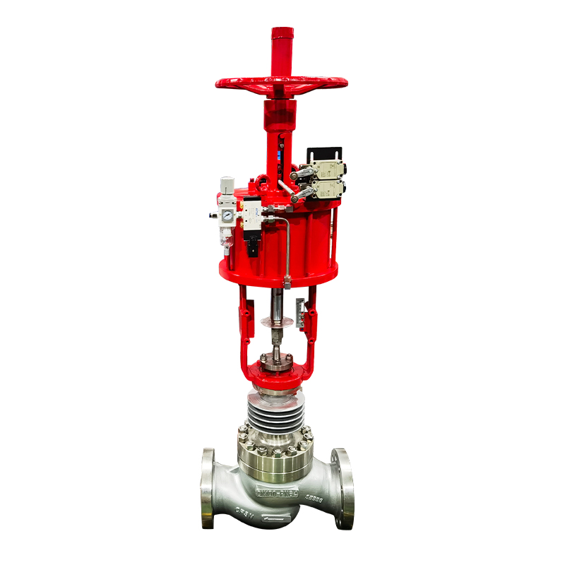
Pneumatic Emergency Shut Off Valve Function and Design
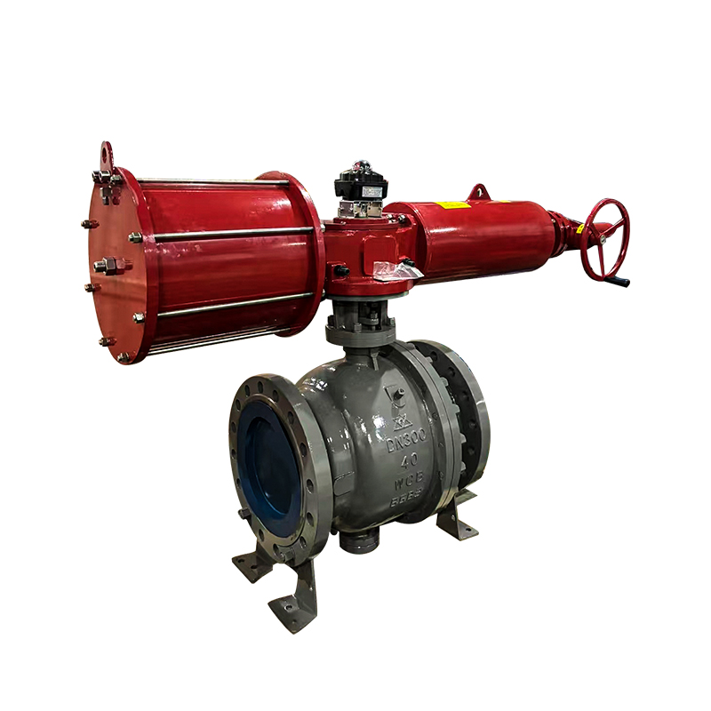
Instant Flow Isolation as the Primary Function
The Pneumatic Emergency Shut Off Valve is designed for one specific purpose: to isolate fluid flow completely and rapidly in response to an emergency signal. Unlike a control valve that manages flow across a range of positions, an emergency shut off valve operates in a binary mode — fully open during normal operation, fully closed on emergency command.
This dedicated function allows the design to be optimized for the two characteristics that matter in emergency shutdown: closing speed and sealing integrity in the closed position. The valve's actuator is sized and configured to drive the valve to the closed position rapidly, and the sealing arrangement is engineered to maintain positive isolation against the differential pressures the valve may encounter after closure.
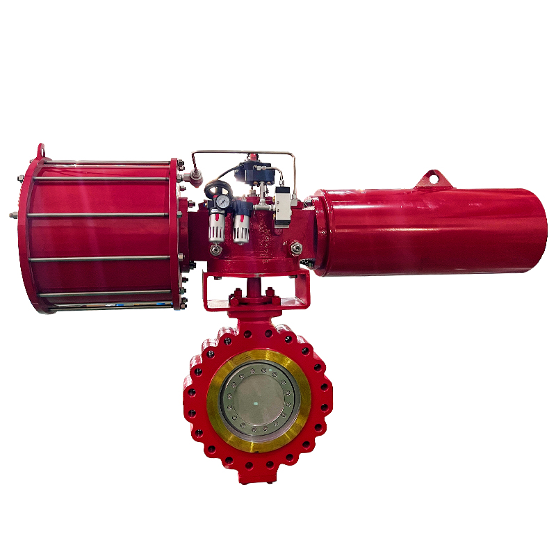
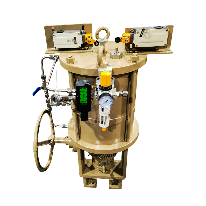
Fail-Safe Closure Mechanisms
Emergency shut off valves in pneumatic systems typically use spring-return actuators that drive the valve to its safe position — closed — when control air or signal is removed. This fail-safe closure means that a power interruption, control air failure, or signal loss automatically commands the valve to close, preventing continued fluid flow even if the initiating event has also disabled other control systems.
The spring force must be sufficient to close the valve fully against the upstream pressure present at the moment of shutdown. This is an important sizing consideration: an actuator that closes reliably at low line pressure may not fully seat the valve against higher line pressures, leaving residual leakage through a partially open valve.
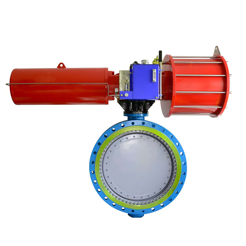
System Protection During Emergency Events
Beyond flow isolation, a well-specified emergency shut off valve protects the system it is installed in by maintaining its closed position reliably against sustained downstream backpressure, withstanding the pressure spike that may occur at the instant of closure as upstream fluid decelerates, and providing an accessible position indicator that confirms closed status to operators and control systems.
These secondary functions often receive less attention during valve selection than the basic flow isolation function, but they determine whether the valve performs reliably over many emergency events rather than degrading after the first few.
Comparing Control Valves and Emergency Shut Off Valves
| Feature | Pneumatic System Control Valve | Pneumatic Emergency Shut Off Valve |
|---|---|---|
| Primary function | Flow regulation across operating range | Complete flow isolation on emergency command |
| Operating positions | Multiple, modulated | Binary — open or closed |
| Closure speed | Configured for controlled closure profile | Optimized for rapid full closure |
| Fail-safe behavior | Configurable — open, closed, or hold | Typically fail-closed via spring return |
| Normal duty | Active during every operating cycle | Standby during normal operation, active only on emergency |
| Reverse flow protection | Depends on design — may include check | Sealing integrity is a primary design requirement |
| Application position | Throughout the control circuit | At critical isolation points — system inlet, hazard boundaries |
These two valve types are complementary rather than interchangeable. A complete emergency shutdown protection system typically uses both: control valves that manage the shutdown sequence and pressure conditions throughout the circuit, and emergency shut off valves that provide positive isolation at the boundaries of protected zones.
Industrial Applications Where Shutdown Leakage Prevention Is Critical
Chemical and Process Plant Environments
Chemical processing systems handle fluids where uncontrolled release during shutdown creates hazards that extend beyond equipment damage — toxic exposure, fire risk, environmental contamination, and regulatory liability. Emergency shutdown in these environments must be both fast and complete, with no leakage at any point in the shutdown sequence.
The valve architectures used in chemical plant emergency shutdown systems reflect this requirement: multiple layers of isolation, active monitoring of valve position throughout the shutdown sequence, and regular proof testing to confirm that valves will perform when called upon.
Pneumatic Automation in Manufacturing
Production automation systems use pneumatic actuation extensively for clamping, conveying, positioning, and assembly operations. Emergency stops in these environments must isolate the pneumatic supply without allowing actuators to drift from their stopped positions in ways that could damage parts or create hazards for maintenance personnel.
Control valves that maintain actuator position during shutdown — by isolating pressure in both chambers of double-acting cylinders rather than venting one side — prevent the uncontrolled actuator movement that creates damage and injury risk during and after emergency stops.
Fluid Transfer and Hydraulic Systems
Hydraulic systems operate at pressures that make uncontrolled fluid release during shutdown a significant equipment damage risk. Hydraulic lines under pressure that are suddenly isolated accumulate fluid hammer effects — pressure spikes caused by the momentum of moving fluid being stopped abruptly.
Emergency shut off valves in hydraulic circuits must be specified to handle both the nominal system pressure and the transient overpressure that fluid hammer generates at the instant of closure. Valves that are rated only for steady-state pressure may be damaged by the transient spike, compromising the isolation they were installed to provide.
Selecting the Right Valve for Emergency Shutdown Protection
Response Time Requirements Vary by Application
The acceptable time from emergency signal to valve closure varies substantially across applications. A safety-critical chemical plant isolation may require closure in a fraction of a second. A production line emergency stop may have a less demanding response requirement where complete closure within a few seconds is acceptable.
Matching valve actuator specifications to the response time requirement — neither over-specifying (which creates unnecessarily fast closure and associated fluid hammer risk) nor under-specifying (which allows too much fluid to pass before isolation is complete) — requires clarity about what the specific application actually needs.
Key selection criteria for emergency shutdown valves:
- Required closure time: determined by the hazard analysis for the application
- Line pressure at shutdown: affects actuator sizing, sealing requirements, and fluid hammer calculations
- Fluid type: determines material compatibility for body, seals, and trim
- Fail-safe direction: closed or open, determined by the failure mode analysis for the process
- Proof testing frequency: valves in safety systems undergo periodic proof tests to confirm operability; the design should accommodate testing without requiring system shutdown
- Position feedback: confirmation that the valve has reached its commanded position is standard in safety-critical applications
System Compatibility and Integration Requirements
Emergency shutdown valves do not operate in isolation — they are part of a control and safety system that monitors conditions, sends commands, and verifies responses. Valve selection must include evaluation of signal compatibility with the control system, actuator supply pressure requirements relative to available instrument air or gas supply, and the physical installation constraints of the location where the valve will be placed.
For systems with existing valve infrastructure, compatibility with installed actuator designs, positioners, and solenoid valve configurations reduces installation complexity and supports consistent maintenance practices across the facility.
Sourcing Pneumatic Valves for Emergency Shutdown Applications
Manufacturing Quality Criteria for Safety-Critical Components
Pneumatic valves used in emergency shutdown service are safety-critical components. The consequences of a valve that fails to close on command, leaks in the closed position, or loses its fail-safe function over time are not limited to equipment inconvenience — they can include process hazards, regulatory consequences, and injury risk to personnel.
Manufacturing quality criteria relevant to safety-critical pneumatic valve procurement:
- Dimensional accuracy and assembly consistency: safety-function valve performance depends on tight tolerances between valve body, seat, and closure element. Manufacturing variation that is acceptable in standard process valves may not be acceptable in safety valve service.
- Material certification: valve body, trim, and seal materials should be traceable to certified material test reports, not just to grade designations on a specification sheet.
- Pressure testing at production: each valve should be leak-tested at or above its rated pressure before leaving the production facility, with test records available as part of the delivery documentation.
- Actuator performance validation: the actuator's ability to close the valve under the specified line pressure conditions should be verified during manufacture, not assumed from design calculations alone.
OEM and Custom Configuration Capability
Industrial safety systems often require valve configurations that do not match standard catalog products: specific body materials for unusual fluid compatibility, non-standard actuator travel or torque characteristics for particular line sizes and pressures, integrated position switches with specific signal types, or mounting configurations dictated by installation geometry.
Suppliers with genuine OEM and custom configuration capability can address these requirements without reverting to workarounds that compromise valve performance. Evaluating a supplier's actual production flexibility — rather than accepting catalog breadth as a proxy for customization capability — is a practical step in sourcing for complex emergency shutdown applications.
Fluid leakage during emergency shutdowns is not an incidental maintenance problem — it is a predictable outcome of pressure dynamics that, without deliberate valve architecture design, resolve themselves through whichever path offers the least resistance. The engineering response to this problem operates at multiple levels simultaneously: system design that controls shutdown sequencing and pressure isolation, control valve selection that provides managed closure profiles rather than abrupt switching, and emergency shut off valve specification that delivers reliable positive isolation at the moments when system behavior is least predictable. None of these elements substitutes for the others, and a system that addresses only one or two of them will still expose itself to the leakage modes that the remaining gaps permit. For engineers and procurement teams specifying pneumatic shutdown systems, the practical path forward begins with understanding which failure mechanisms are present in the specific application and working backward to the valve and system configurations that address them. Zhejiang Wisley Automatic Valve Co., Ltd. manufactures a range of pneumatic control valves and emergency shut off valve configurations designed for industrial shutdown safety applications, with engineering support, material certification documentation, and OEM customization capability available for project-specific procurement requirements.