In industrial process systems, the speed of a valve response can be the difference between a controlled shutdown and a cascading failure. Manual valves depend on an operator being present and reacting quickly. Electric actuators introduce response lag tied to motor ramp-up and control signal latency. When a production line, chemical dosing system, or compressed air circuit needs to close in a fraction of a second — reliably, repeatedly, without hesitation — the engineering choice shifts toward pneumatic actuation. The Pneumatic Stop Valve is built specifically for this demand: a flow shut-off device driven by compressed air, capable of fast and consistent actuation across high-cycle industrial environments.
What Is a Pneumatic Stop Valve?
Compressed Air as the Actuation Medium
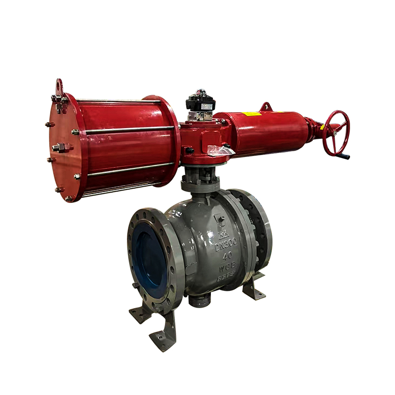
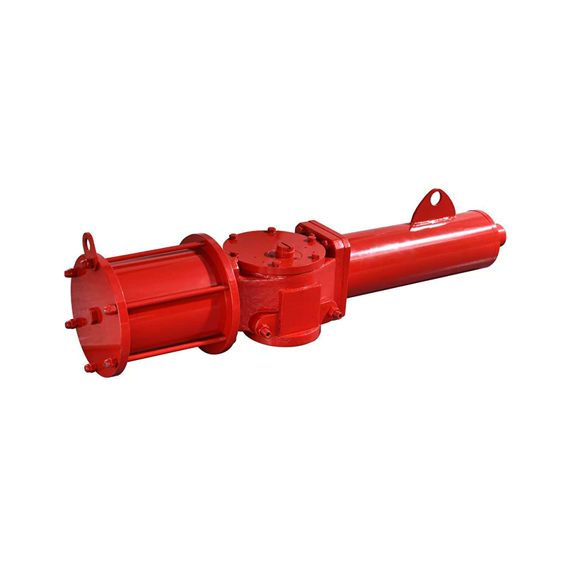
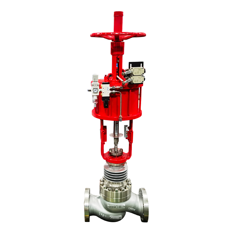
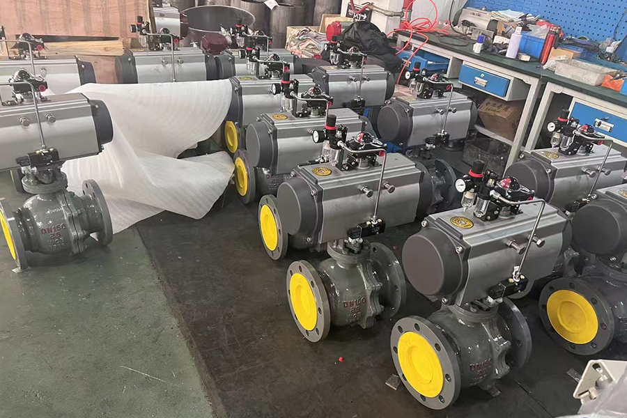
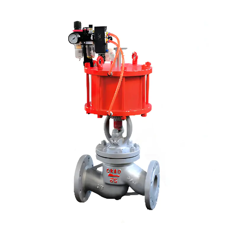
A pneumatic stop valve is a flow control device in which the opening and closing action is powered by compressed air rather than manual force or an electric motor. Compressed air enters an actuator — either a piston-type or diaphragm-type — and the resulting mechanical motion moves the valve stem, which in turn opens or closes the flow path through the valve body.
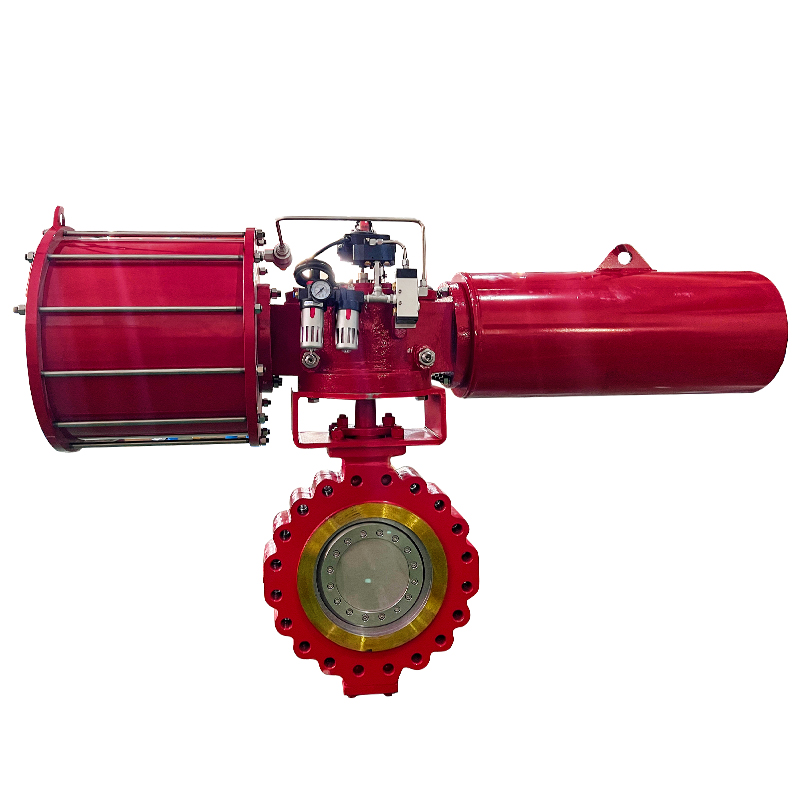
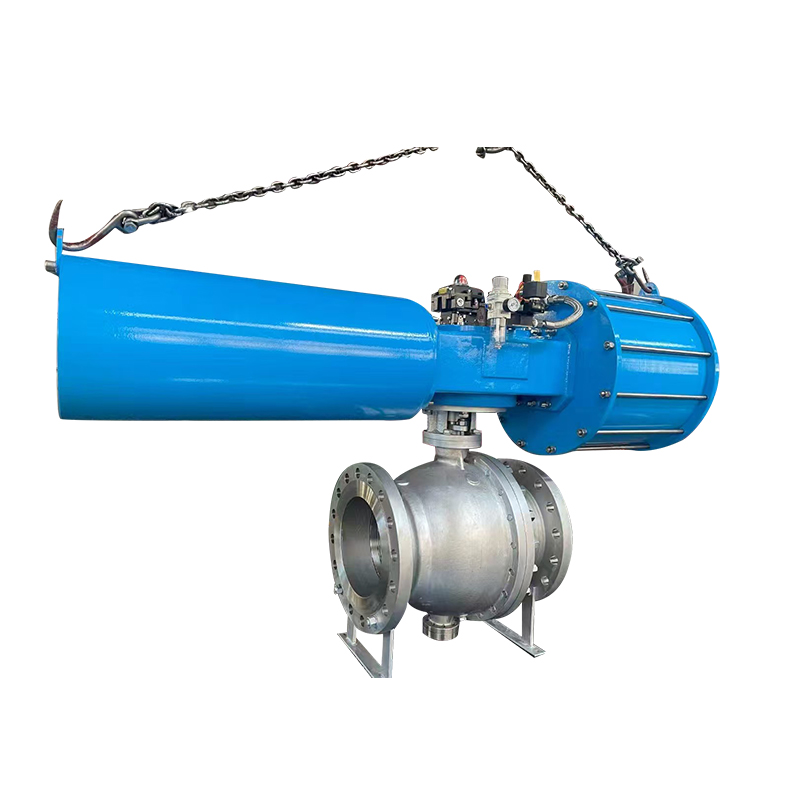
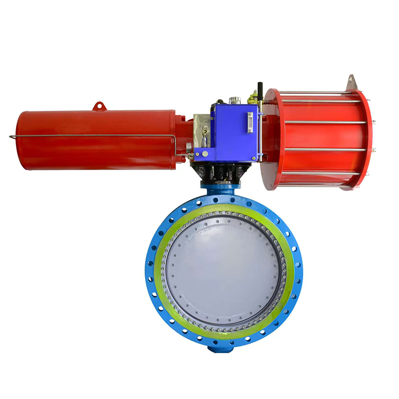
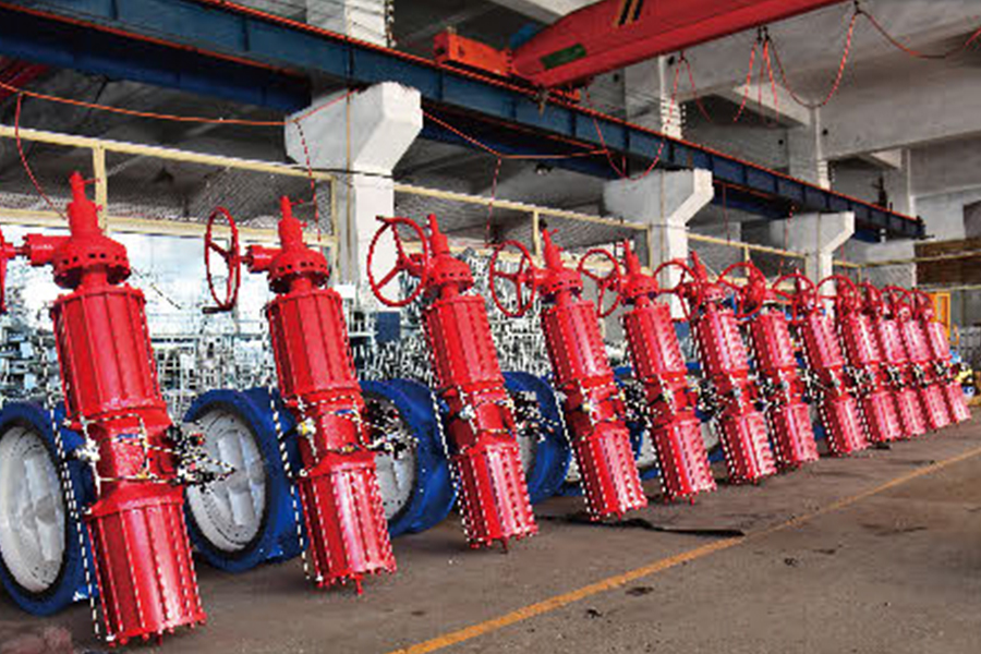
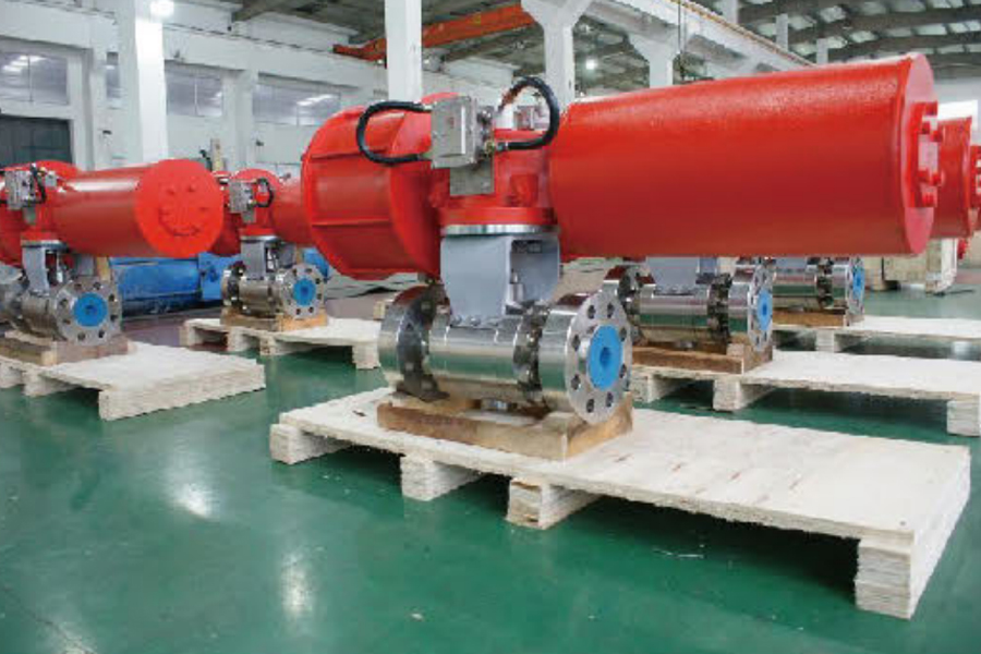
The valve body itself can take several forms: globe, ball, butterfly, or angle body configurations, depending on the application. What defines this category is the actuator — the pneumatic driver — rather than the valve body shape. The combination of a reliable body design with a pneumatically powered actuator is what gives these valves their speed and automation compatibility.
How Does the Actuation Mechanism Work?
From Air Signal to Valve Position
The sequence from control signal to physical valve movement is short and direct. Understanding it helps clarify both the speed advantage and the failure mode considerations.
- A solenoid valve receives an electrical signal from a PLC or control system
- The solenoid directs compressed air into the actuator chamber
- Air pressure acts on the piston or diaphragm inside the actuator
- The resulting force pushes or pulls the valve stem
- The stem moves the valve element (ball, disc, plug, or globe) to the open or closed position
- When the signal reverses, air is vented from the actuator and the valve returns to its default position
The entire sequence — from signal to full valve travel — happens in a time frame that electric actuators typically cannot match, particularly in larger valve sizes where motor torque and ramp-up time become limiting factors.
Why Is Speed Important in Industrial Flow Control?
Where Response Time Has Real Consequences
Not every valve application is time-sensitive. A valve on a slow fill tank can take several seconds to close without consequence. But a significant portion of industrial flow control scenarios involve conditions where delayed response compounds the problem:
- Emergency shut-off on chemical injection lines — a delayed close allows continued dosing into a process that has already tripped
- Surge protection on pipeline systems — rapid valve actuation prevents pressure waves from propagating downstream
- Safety interlock circuits — process safety systems rely on valves that respond within defined time windows to be effective
- High-cycle packaging and filling machinery — equipment running hundreds of cycles per hour needs valve actuation that keeps pace without mechanical fatigue
- Compressed air and gas supply lines — sudden demand changes require fast isolation to protect downstream equipment
In these contexts, pneumatic actuation is specified not as a preference but as a functional requirement.
Fail-Safe Design: What Happens When Air Pressure Is Lost?
Spring Return and the Logic of Default Position
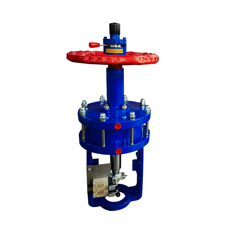
One of the more important design considerations for any automated valve is what it does when the power source fails. For electric valves, power loss typically means the valve stays wherever it was. For pneumatic systems, engineers have more control over this behavior through spring-return actuator design.
A spring-return actuator incorporates a compressed spring on one side of the piston or diaphragm. When air pressure is applied, the actuator works against the spring to move the valve. When air pressure drops or is cut — whether by design or by system failure — the spring drives the valve back to its default position.
Two configurations cover most industrial applications:
- Fail-closed (normally closed) — air opens the valve; loss of air closes it. Used where the safe state is "no flow" — chemical injection, fuel lines, process isolation
- Fail-open (normally open) — air closes the valve; loss of air opens it. Used where the safe state is "flow continues" — cooling water supply, seal flush systems
Selecting the correct fail-safe configuration at the design stage is not optional. It is a safety engineering decision that should reflect the consequences of each failure mode for the specific process.
Integration With Automated Control Systems
Pneumatic Valves as Execution Nodes in a Larger System
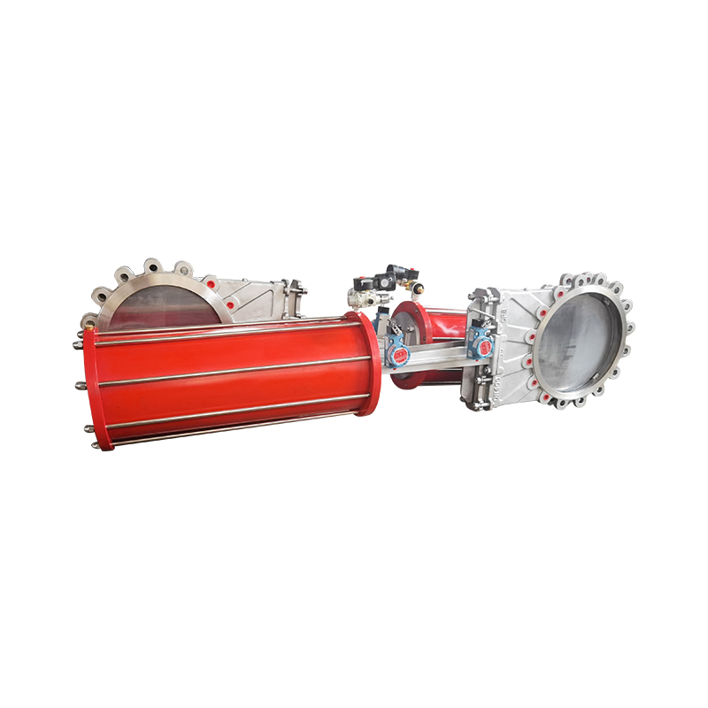
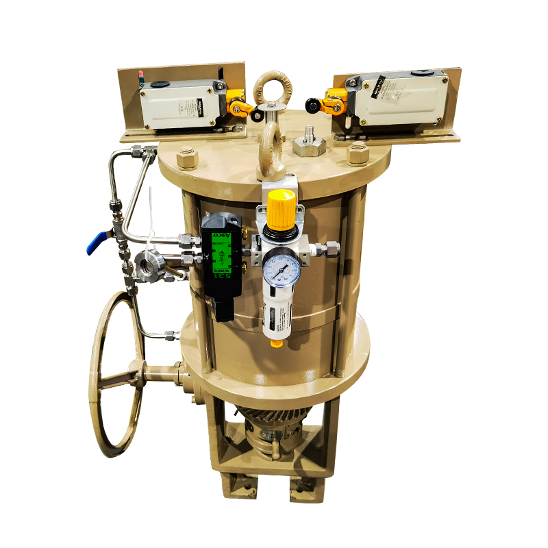
A pneumatic stop valve does not operate in isolation in modern industrial environments. It is one component in a control loop that typically includes a PLC or DCS, a solenoid valve, position feedback sensors, and sometimes a positioner for proportional control.
The solenoid valve is the interface between the electrical control signal and the pneumatic actuator. When the PLC sends an output signal, the solenoid opens or shifts to direct air into the actuator. The valve moves. A position switch or proximity sensor confirms the valve has reached the commanded position and sends a feedback signal back to the control system.
This closed-loop arrangement allows the control system to verify that the valve actually moved — not just that the command was sent. In safety-critical applications, that confirmation signal is part of the safety function, not just a convenience.
Variable air supply pressure can also affect actuation force and speed, which is why many installations include a pressure regulator in the air supply line to the actuator. Consistent supply pressure produces consistent valve response.
Comparing Pneumatic, Electric, and Manual Valve Actuation
Each actuation method has genuine strengths, and the choice between them should be driven by application requirements rather than default preference.
Pneumatic actuation sits at the intersection of speed, reliability, and mechanical simplicity. It does not require complex electronics in the actuator itself, which reduces failure points in harsh environments. Electric actuators offer advantages in precise position control and in facilities where compressed air infrastructure is not available. Manual valves remain appropriate for maintenance isolation points and applications with infrequent operation cycles.
What Makes a Pneumatic Stop Valve Reliable Over Time?
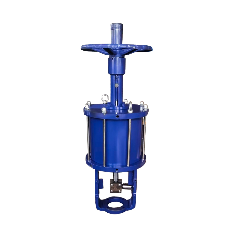
Structural Simplicity and Its Advantages
Reliability in an industrial valve comes from having fewer parts that can fail, and having the parts that remain built to withstand the operating conditions they will actually encounter. Pneumatic actuators have an inherently simpler internal structure than electric actuators — no motor windings, no gearboxes, no encoders. The moving parts are a piston or diaphragm, a stem, and a spring. That simplicity translates into durability in high-cycle environments.
Key factors that affect long-term reliability:
- Actuator seal condition — O-rings and diaphragm seals in the actuator degrade over time, particularly with contaminated air supply. Proper air filtration and lubrication upstream extends seal life considerably
- Valve body and trim material — body material must resist the process fluid; trim material must handle the pressure differential across the closed valve without deformation or erosion
- Spring fatigue in spring-return actuators — springs cycle with every valve operation; material quality and spring design determine how many cycles are possible before replacement is needed
- Stem packing — the packing that seals around the valve stem prevents process fluid from leaking out; worn packing causes external leakage and requires periodic adjustment or replacement
Maintenance intervals for pneumatic stop valves in clean air service can be long. The same valve in a dirty or corrosive environment needs more frequent inspection. Matching the maintenance schedule to the actual operating conditions is how reliability is sustained rather than assumed.
Which Industries Depend on Pneumatic Stop Valves?
Application Environments Where Fast Actuation Is Non-Negotiable
Chemical and petrochemical processing — process lines carrying reactive, corrosive, or flammable fluids require valves that respond quickly to process upsets. Emergency shut-down systems in these facilities typically specify pneumatic actuation with spring-return fail-closed design.
Food and beverage production — hygienically designed pneumatic valves control product flow, clean-in-place (CIP) cycles, and steam sterilization sequences. Cycle counts in food production environments are high, and sanitary design standards add requirements for surface finish and material certification.
Pharmaceutical manufacturing — similar to food and beverage but with stricter contamination control requirements. Actuator venting must be managed to prevent contamination of clean environments.
Water and wastewater treatment — pump protection, filter backwash, and dosing system control all use pneumatically actuated stop valves. The fail-safe behavior is particularly important in treatment plants where loss of a dosing valve in the wrong position has consequences for treated water quality.
Automotive and general manufacturing — assembly line fluid control, cooling circuit management, and compressed air distribution all use pneumatic stop valves in high-cycle applications.
Packaging machinery — filling, sealing, and labeling equipment operates at high speed and needs valve actuation that matches the machine cycle rate without creating a bottleneck.
Sizing and Selection: What Gets Overlooked
The Details That Determine Whether the Valve Performs as Expected
Specifying a pneumatic stop valve involves more than selecting a body size and pressure rating. Several factors are routinely underspecified and then corrected after installation:
- Actuator sizing against supply pressure — the actuator must generate enough force at the available supply pressure to overcome the valve's breakaway torque or stem force, plus a reasonable safety margin
- Flow coefficient (Cv) matching — the valve must pass the required flow at the available pressure differential without excessive velocity that causes noise, erosion, or cavitation
- End connection compatibility — threaded, flanged, and clamp-type connections each suit different installation contexts; specifying the wrong type creates rework at installation
- Temperature range of seat and seal materials — PTFE seats and standard O-rings have temperature limits; steam service or cryogenic applications need material specifications that reflect actual operating temperatures
- Position feedback requirements — if the control system requires confirmation of valve position, the actuator must be fitted with position switches or a positioner at the time of order
Addressing these points in the specification stage, rather than during commissioning, is how installation projects stay on schedule.
Working With a Supplier Who Understands the Application
Selecting a pneumatic stop valve from a catalog is only part of the procurement process. The actuation configuration, fail-safe behavior, body and seat material selection, and integration requirements all need to match the specific operating context — and those details are rarely fully captured in a standard product listing. Zhejiang Wisley Automatic Valve Co., Ltd. develops pneumatic valve products for industrial automation environments, with a product range covering stop valves, actuator configurations, and control accessories suited to process industries including chemical, food and beverage, pharmaceutical, and general manufacturing. Their engineering team can support application review and specification development for projects where valve selection carries process safety or automation integration requirements. If you are evaluating pneumatic shut-off solutions for a new installation or a system upgrade, reaching out to discuss the application details is a straightforward way to move from catalog selection to a solution that actually fits the process.